Fiber Optic Vibration Sensor
We describe a very sensitive sensor design that can be used to detect abnormal vibrations of machines or parts in industrial machines or even as general purpose alarms by detecting abrupt movement. The different in this design is the sensor system that makes use of a piece of fiber optics which the very sensitive forna. In addition to the practical purposes for its efficiency and simplicity, the circuit also has teaching applications and can be used in electronics, mechatronics and telecommunications courses to serve as an example of applications and operation of optical fibers and also as shield sensor.
Small pieces of fiber optics can be obtained with ease from a variety of sources, such as samples from manufacturers, decorative lamps and other places (at one of the electronics fairs in São Paulo, a fiber optic manufacturer distributed a huge quantity of small pieces of optical fibers to visitors and could be used in this assembly).
If the reader has a small piece of common optical fiber, mounting this unit will not cause any further difficulties. If the reader works with communications certainly get a fiber optic piece of a few inches will not be a hindrance to the realization of this project.
The basic idea of the project is to critically focus a beam of light on an optical fiber so that it hits a photo sensor.
As the fiber gets suspended only by one end, it will swing the position strip causing the sensor to stop receiving the light and thus triggering a timed circuit. In figure 1 we give an idea of how this can be done.
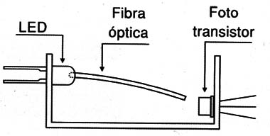
Since the emitter (fiber and LED) and receiver can be far from the trip circuit, the sensor or alarm can be used in many practical applications involving the protection of objects and locations or monitoring the operation of industrial and other equipment.
Of course, for demonstrative purposes all elements can be mounted in the same place and in place of the relay one can use a small buzzer or audio oscillator as output.
In figure 2 we show how this can be done.
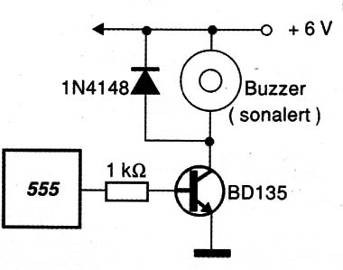
The tone of the oscillator given as an example is adjusted by a trimpot.
HOW IT WORKS
LED1 is the light source that is coupled to a small piece of fiber optic. The optical fiber is embedded in a small hole made in the plastic housing of the LED itself and secured with a drop of strong glue so that the light radiation appears at its other end.
Positioned so that the free end is aligned with a photo-transistor, the fiber keeps this sensor illuminated and therefore driving.
The emitter current of the phototransistor is applied to the base of a second transistor (Q1) so as to keep it in conduction and therewith pin 2 of the integrated circuit 555 at the high level.
In these conditions, the integrated circuit, which is configured as a monostable multivibrator, remains off.
When a small vibration causes the optical fiber to oscillate, the focus of light stops focusing on the sensor and with that the photo-transistor goes to the cut.
The result is that Q1 has its emitter current reduced to the point where it takes the pin 2 of the integrated circuit to the low level because the voltage drops and with that its firing occurs.
Upon tripping, the output of integrated circuit 555 goes to high level for a time interval which depends both on the setting of P1 as well as on the value of capacitor C1.
With the indicated component values, this time can be up to two minutes. However, if the reader wants longer tripping intervals, capacitor C1 can be increased. The recommended maximum value of this capacitor is around 1 500 μF, as larger values show leaks that can destabilize the circuit operation.
At the output of the 555 we have a transistor that, when in driving, excites the coil of a small relay. This relay, depending on the characteristics of your contacts, can trigger warning systems from large powers.
The circuit is powered by a voltage of 6 V that can be sourced by source or battery (batteries).
As this battery should keep the LED on, which means a current between 20 and 50 mA, depending on the R4 value and the sensitivity of the sensor, in applications where the system is to be connected for a long time it is not recommended to use more batteries. yes from source.
This source must have a voltage according to the relay used and a current in the range of 200 to 500 mA. It is recommended to use stabilized source.
However, in demonstrations, when the circuit is turned on briefly, small or medium stacks can be used.
ASSEMBLY
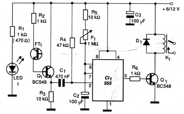
In figure 3 we have the complete diagram of the alarm.
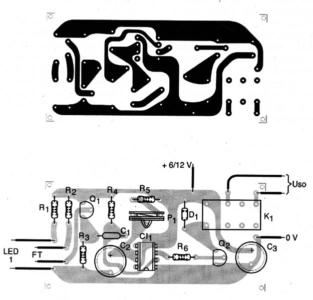
 The arrangement of the components on a printed circuit board is shown in figure 4.
 The resistors are all 1/8 W or larger and the capacitors must have minimum working voltages of 6 V. The trimpot can be replaced by a potentiometer in the experimental setup, in order to achieve the variation of the tripping time.
The resistor R3 can be changed in the range of 10kΩ to 100kΩ to obtain greater sensitivity in case of difficulties of focusing the fiber in the phototransistor.
Any phototransistor can be used, including Darlington types that will provide greater sensitivity.
The relay can be of any low cost type with 6 or 12 V coil voltage and maximum 50 mA current, and if the base is different from the original, changes to the design of the printed circuit board must be made.
The critical point of the assembly is the sensor.
In the common round red LED the reader must carefully drill a hole with a 1mm thick drill bit. This hole must penetrate just enough to allow the fiber to fit, and can in no way reach the emitter semiconductor chip, as shown in figure 5. If this happens the LED will be damaged no longer working.
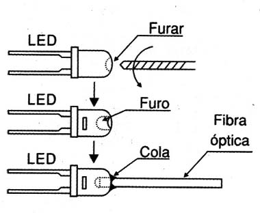 Attached the fiber can be held in position with a drop of some strong glue (Super Bonder, for example).
After coupling the LED to the fiber it will be interesting to power the 6 V LED and a 470 Ω resistor in series and verify that the light emitted appears at the end of the fiber. See that R1 in series with the LED should be 470 Ω if the power is made with 6 V and 1 kΩ if the power is made with 12 V.
Both the LED and the Photo Transistor are held on a printed circuit board. The LED should be positioned so that the fiber has its other end aligned with the phototransistor as shown in Figure 5 itself.
It will be interesting to mount this system protected from ambient light to prevent it from affecting the photo sensor and thus cause a loss of sensitivity of the circuit.
PROOF AND USE
To prove it is enough to turn on the circuit and initially put the trimpot P1 in the position of least resistance. The fiber must be in line with the photo sensor.
Relay tripping may occur at the time the power is established, but a few seconds later, with light coming into the photo sensor, the relay must be deactivated.
By moving lightly on the fiber or swinging the sensor, the circuit should trip.
If this does not occur, change the value of R3. If desired, you can use a 1 M ohm trimpot instead of this component to obtain a sensitivity adjustment.
Once the sensor has been tested, it is only necessary to permanently install the sensor where it is necessary to detect any balance.
If the sensor has the part of the fiber unprotected it becomes also sensitive to the small currents of air and the system can serve to detect "wind".
For use in industrial machines, simply mount the sensor where the vibration is to be detected.
The length of the fiber determines the amplitude of the vibrations that can be detected. Depending on the application the fiber can have its length changed. It will be convenient to experiment with the ideal length for the intended application.
Another interesting possibility of use is to connect two photo-transistors in series in order to obtain an Optical E-Gate. With two fibers coupled to these photo-transistors we will activate the system only when vibrations in two places or in two modes are detected.
If one of the sensors is in a vertical and a horizontal position, for example, we will have a configuration that only detects combined vibrations.
Semiconductors:
FT1 - Photo-transistor - see text
CI-1 - 555 - integrated circuit
Q1, Q2 - BC548 or equivalent - general purpose NPN transistor
LED1 - Common red LED - see text
D1 - 1N4148 - general purpose diode
Resistors: (1 / 8W, 5%)
R1 - 1 kΩ (12 V), 470 Ω (6 V) - see text
R2, R6 - 1kΩ
R3 - 10 kΩ - see text
R4 - 47 kΩ
R5 - 10 kΩ
P1 - 1 M Ω
Capacitors:
C1 - 470 nF - polyester or ceramic
C2, C3 - 100 μF / 6V - electrolytic
Several:
FO - optical fiber - see text
K1 - 6 V or 12 V relay with 50 mA coil - see text
S1 - Single switch
B1 - 6 V - 4 batteries or power supply
Printed circuit board, mounting box, battery holder or power supply, wires, solder, etc.
Small pieces of fiber optics can be obtained with ease from a variety of sources, such as samples from manufacturers, decorative lamps and other places (at one of the electronics fairs in São Paulo, a fiber optic manufacturer distributed a huge quantity of small pieces of optical fibers to visitors and could be used in this assembly).
If the reader has a small piece of common optical fiber, mounting this unit will not cause any further difficulties. If the reader works with communications certainly get a fiber optic piece of a few inches will not be a hindrance to the realization of this project.
The basic idea of the project is to critically focus a beam of light on an optical fiber so that it hits a photo sensor.
As the fiber gets suspended only by one end, it will swing the position strip causing the sensor to stop receiving the light and thus triggering a timed circuit. In figure 1 we give an idea of how this can be done.

Since the emitter (fiber and LED) and receiver can be far from the trip circuit, the sensor or alarm can be used in many practical applications involving the protection of objects and locations or monitoring the operation of industrial and other equipment.
Of course, for demonstrative purposes all elements can be mounted in the same place and in place of the relay one can use a small buzzer or audio oscillator as output.
In figure 2 we show how this can be done.

The tone of the oscillator given as an example is adjusted by a trimpot.
HOW IT WORKS
LED1 is the light source that is coupled to a small piece of fiber optic. The optical fiber is embedded in a small hole made in the plastic housing of the LED itself and secured with a drop of strong glue so that the light radiation appears at its other end.
Positioned so that the free end is aligned with a photo-transistor, the fiber keeps this sensor illuminated and therefore driving.
The emitter current of the phototransistor is applied to the base of a second transistor (Q1) so as to keep it in conduction and therewith pin 2 of the integrated circuit 555 at the high level.
In these conditions, the integrated circuit, which is configured as a monostable multivibrator, remains off.
When a small vibration causes the optical fiber to oscillate, the focus of light stops focusing on the sensor and with that the photo-transistor goes to the cut.
The result is that Q1 has its emitter current reduced to the point where it takes the pin 2 of the integrated circuit to the low level because the voltage drops and with that its firing occurs.
Upon tripping, the output of integrated circuit 555 goes to high level for a time interval which depends both on the setting of P1 as well as on the value of capacitor C1.
With the indicated component values, this time can be up to two minutes. However, if the reader wants longer tripping intervals, capacitor C1 can be increased. The recommended maximum value of this capacitor is around 1 500 μF, as larger values show leaks that can destabilize the circuit operation.
At the output of the 555 we have a transistor that, when in driving, excites the coil of a small relay. This relay, depending on the characteristics of your contacts, can trigger warning systems from large powers.
The circuit is powered by a voltage of 6 V that can be sourced by source or battery (batteries).
As this battery should keep the LED on, which means a current between 20 and 50 mA, depending on the R4 value and the sensitivity of the sensor, in applications where the system is to be connected for a long time it is not recommended to use more batteries. yes from source.
This source must have a voltage according to the relay used and a current in the range of 200 to 500 mA. It is recommended to use stabilized source.
However, in demonstrations, when the circuit is turned on briefly, small or medium stacks can be used.
ASSEMBLY
In figure 3 we have the complete diagram of the alarm.


The resistor R3 can be changed in the range of 10kΩ to 100kΩ to obtain greater sensitivity in case of difficulties of focusing the fiber in the phototransistor.
Any phototransistor can be used, including Darlington types that will provide greater sensitivity.
The relay can be of any low cost type with 6 or 12 V coil voltage and maximum 50 mA current, and if the base is different from the original, changes to the design of the printed circuit board must be made.
The critical point of the assembly is the sensor.
In the common round red LED the reader must carefully drill a hole with a 1mm thick drill bit. This hole must penetrate just enough to allow the fiber to fit, and can in no way reach the emitter semiconductor chip, as shown in figure 5. If this happens the LED will be damaged no longer working.

After coupling the LED to the fiber it will be interesting to power the 6 V LED and a 470 Ω resistor in series and verify that the light emitted appears at the end of the fiber. See that R1 in series with the LED should be 470 Ω if the power is made with 6 V and 1 kΩ if the power is made with 12 V.
Both the LED and the Photo Transistor are held on a printed circuit board. The LED should be positioned so that the fiber has its other end aligned with the phototransistor as shown in Figure 5 itself.
It will be interesting to mount this system protected from ambient light to prevent it from affecting the photo sensor and thus cause a loss of sensitivity of the circuit.
PROOF AND USE
To prove it is enough to turn on the circuit and initially put the trimpot P1 in the position of least resistance. The fiber must be in line with the photo sensor.
Relay tripping may occur at the time the power is established, but a few seconds later, with light coming into the photo sensor, the relay must be deactivated.
By moving lightly on the fiber or swinging the sensor, the circuit should trip.
If this does not occur, change the value of R3. If desired, you can use a 1 M ohm trimpot instead of this component to obtain a sensitivity adjustment.
Once the sensor has been tested, it is only necessary to permanently install the sensor where it is necessary to detect any balance.
If the sensor has the part of the fiber unprotected it becomes also sensitive to the small currents of air and the system can serve to detect "wind".
For use in industrial machines, simply mount the sensor where the vibration is to be detected.
The length of the fiber determines the amplitude of the vibrations that can be detected. Depending on the application the fiber can have its length changed. It will be convenient to experiment with the ideal length for the intended application.
Another interesting possibility of use is to connect two photo-transistors in series in order to obtain an Optical E-Gate. With two fibers coupled to these photo-transistors we will activate the system only when vibrations in two places or in two modes are detected.
If one of the sensors is in a vertical and a horizontal position, for example, we will have a configuration that only detects combined vibrations.
Semiconductors:
FT1 - Photo-transistor - see text
CI-1 - 555 - integrated circuit
Q1, Q2 - BC548 or equivalent - general purpose NPN transistor
LED1 - Common red LED - see text
D1 - 1N4148 - general purpose diode
Resistors: (1 / 8W, 5%)
R1 - 1 kΩ (12 V), 470 Ω (6 V) - see text
R2, R6 - 1kΩ
R3 - 10 kΩ - see text
R4 - 47 kΩ
R5 - 10 kΩ
P1 - 1 M Ω
Capacitors:
C1 - 470 nF - polyester or ceramic
C2, C3 - 100 μF / 6V - electrolytic
Several:
FO - optical fiber - see text
K1 - 6 V or 12 V relay with 50 mA coil - see text
S1 - Single switch
B1 - 6 V - 4 batteries or power supply
Printed circuit board, mounting box, battery holder or power supply, wires, solder, etc.
评论
发表评论